1.5 The minimum manufacturing data pack
A manufacturing line runs primarily on data. The most common cause of production delays is not machine failure or component shortages—it is incomplete or ambiguous documentation. The Manufacturing Data Pack serves as the formal contract between the engineering team and the factory. When the data is unclear, the factory is forced to either guess, which introduces high risk, or stop production entirely, which incurs high costs.
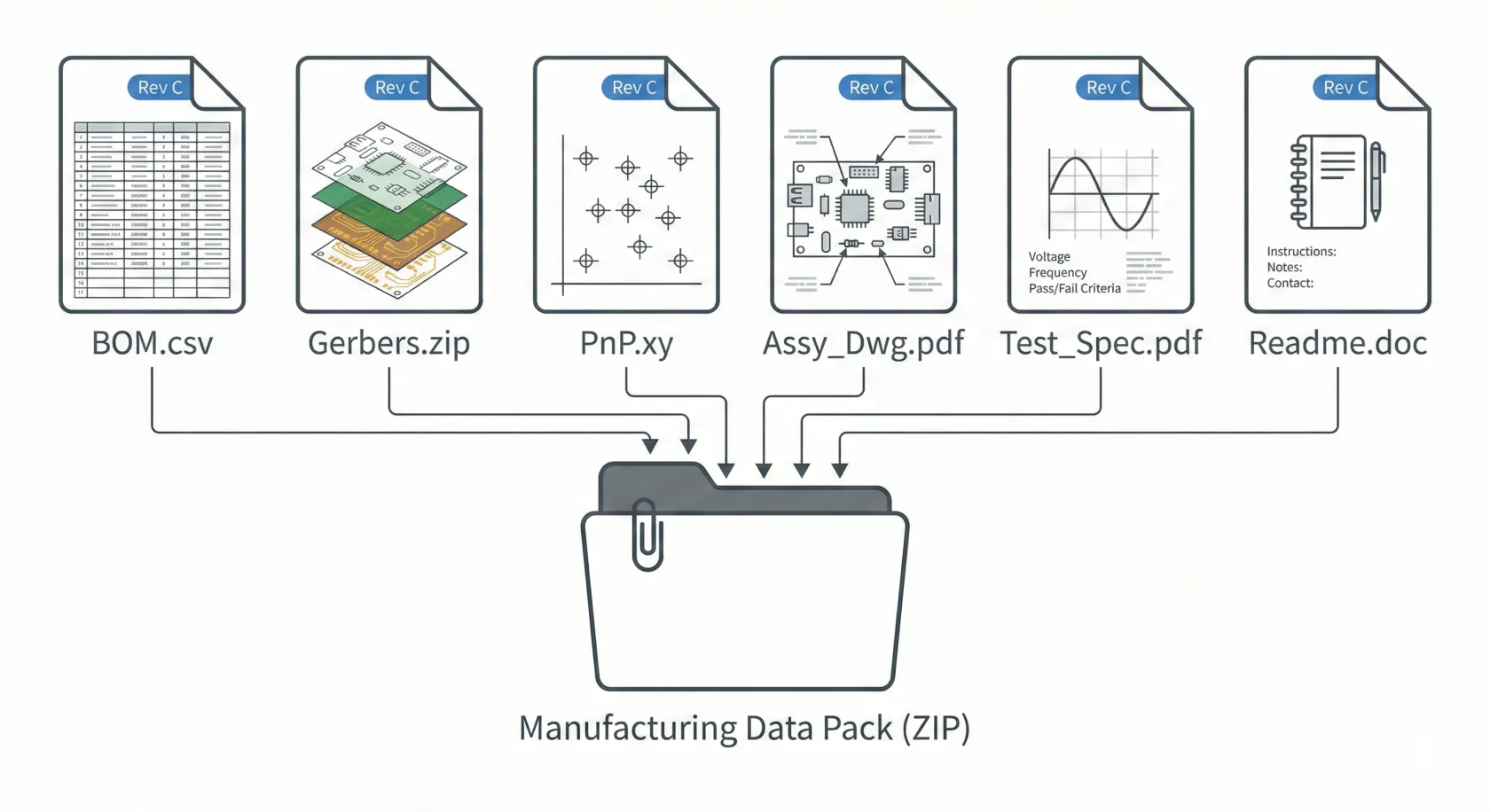
Successfully launching a build requires a specific set of files that clearly define the physical, electrical, and commercial reality of the product.
1. The Bill of Materials (BOM)
Section titled “1. The Bill of Materials (BOM)”Definition: The recipe. It lists every single component required to build one unit.
The engineering reality
Section titled “The engineering reality”The BOM drives the entire supply chain. It must be provided in a machine-readable format, such as Excel or CSV, rather than a static PDF.
- Must Include: Manufacturer Part Number (MPN), Quantity Per Board, Reference Designator (e.g., R1, C4), and a clear Description.
- The Risk: Ambiguous MPNs, such as simply listing “10k Resistor,” force the procurement team to guess. This frequently results in selecting the cheapest available option, which may have incorrect tolerance or power ratings for the specific circuit.
2. Gerber files (RS-274X)
Section titled “2. Gerber files (RS-274X)”Definition: The blueprints. These are vector files that explicitly tell the PCB fabrication machines where to etch copper, drill holes, and print solder mask.
The engineering reality
Section titled “The engineering reality”Gerbers are layer-specific. Separate, clearly named files are required for the Top Copper, Bottom Copper, Drill Hit Data, Solder Paste, and Silkscreen layers.
- The Risk: Without the precise Solder Paste layer data, the factory cannot cut a stencil, and SMT assembly simply cannot start. Similarly, if the Drill file is separated from the Drill Tool list, the factory might drill holes with incorrect diameters.
3. Centroid file (Pick & Place / CPL)
Section titled “3. Centroid file (Pick & Place / CPL)”Definition: The navigation map. This text file contains the exact coordinate position (X, Y) and rotation (Theta) of every single component on the board.
The engineering reality
Section titled “The engineering reality”SMT machines are robotic systems; they do not “see” the board in a holistic way. Instead, they move to specified coordinates relative to a designated origin point (0,0).
- The Risk: If the rotation data is incorrect—for instance, specifying 90° instead of -90°—polarized components like diodes and ICs will be placed backwards, leading to immediate short circuits upon power-up.
4. Assembly drawings
Section titled “4. Assembly drawings”Definition: The visual guide. Usually a PDF showing component locations, polarity markings, and any special manual assembly instructions, such as “Install J2 after cleaning.”
The engineering reality
Section titled “The engineering reality”This document is primarily for the human operators. Quality Inspectors use it to visually verify what the automated machines did. It acts as the final check against “invisible” data errors.
- The Risk: When polarity marks on the physical silkscreen are covered by the component body itself, the Assembly Drawing becomes the only reliable reference for verifying correct orientation during inspection.
5. Readme / fabrication notes
Section titled “5. Readme / fabrication notes”Definition: The metadata. A text or PDF file detailing the specific board physical requirements: PCB thickness (1.6mm is standard, but should still be stated), copper weight (1oz vs 2oz), surface finish (ENIG vs HASL), and solder mask color.
The engineering reality
Section titled “The engineering reality”Without this defining file, a Fab House will naturally default to the cheapest standard options available.
- The Risk: Omitting explicit Impedance Control requirements for high-speed signals leads the Fab House to ignore necessary trace width precision, which can cause radio or WiFi circuit failures.
The risk of poor revision control
Section titled “The risk of poor revision control”The most dangerous file in a factory environment is often an outdated version of the correct file.
Every file name should contain a clear revision code, such as “ProjectX_BOM_Rev02.” For example, updating a board connector to Revision 2 while mistakenly releasing the Revision 1 Bill of Materials (BOM) causes the purchasing team to procure the obsolete connector. This obsolete part will fail to fit the new bare boards, resulting in scrapped material and lost time.
Recap: Minimum Manufacturing Data Pack
Section titled “Recap: Minimum Manufacturing Data Pack”| Document | Mandatory Content | Format / Requirement | Critical Risk if Non-Compliant |
|---|---|---|---|
| Bill of Materials (BOM) | MPN, Quantity, RefDes, Description. Include “Alternates/Substitutes” column. | Machine-readable (Excel/CSV). | Procurement of incorrect or out-of-spec components. |
| Gerber Files (RS-274X) | Separate files for all layers: Top/Bottom Copper, Drill Data, Solder Paste, Silkscreen. | Clearly named, layer-specific files. | Inability to fabricate stencil or PCB; drilling errors. |
| Centroid File (CPL) | X, Y, Theta (rotation) for every component. | Text file with coordinates relative to board origin (0,0). | Polarized components (diodes, ICs) placed backwards, causing shorts. |
| Assembly Drawing | Component locations, polarity markings, special manual instructions. | PDF for visual reference by Quality Inspectors. | Incorrect manual assembly; inability to verify automated placement. |
| Fabrication Notes | PCB thickness, copper weight, surface finish, solder mask color, impedance control. | Explicitly stated in text/PDF file. | Fab defaults to cheap standards; high-speed circuit failure. |
| Revision Control | Clear revision code (e.g., ProjectX_BOM_Rev02). | Embedded in every file name. | Procurement and installation of obsolete components. |