1.5 The Minimum Manufacturing Data Pack
A manufacturing line does not run on good intentions; it runs on data. The most common cause of production delay is not a machine failure or a component shortage—it is incomplete documentation. The "Manufacturing Data Pack" is the contract between the designer and the factory. If the data is ambiguous, the factory will either guess (high risk) or stop (high cost).
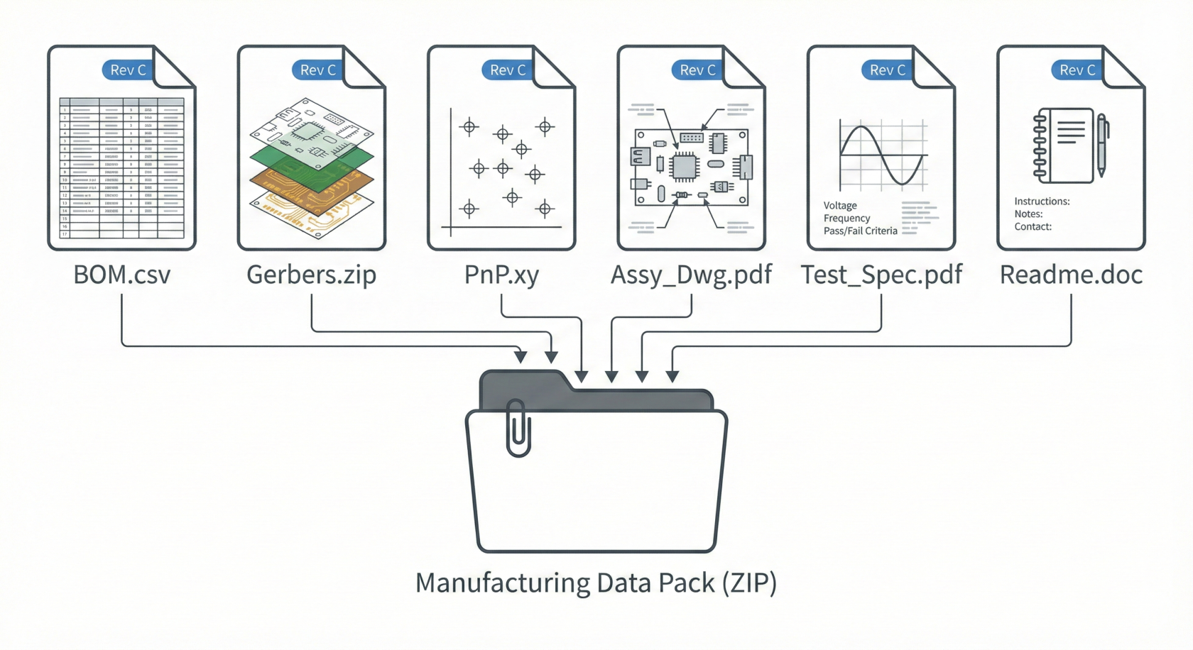
To launch a build, you must provide a specific set of files that define the physical, electrical, and commercial reality of the product.
1. The Bill of Materials (BOM)
Definition: The recipe. It lists every single component required to build one unit.
The Engineering Reality
The BOM drives the supply chain. It must be machine-readable (Excel/CSV), not a PDF.
- Must Include: Manufacturer Part Number (MPN), Quantity per board, Reference Designator (e.g., R1, C4), and Description.
- If the MPN is ambiguous (e.g., "10k Resistor") → Then the procurement team will guess, likely choosing the cheapest option with the wrong tolerance or power rating.
Pro-Tip: Always include a column for "Alternates/Substitutes." If the primary part is out of stock (common), a pre-approved alternate allows the factory to proceed without stopping for engineering approval.
2. Gerber Files (RS-274X)
Definition: The blueprints. These are vector files that tell the PCB fabrication machines exactly where to etch copper, drill holes, and print solder mask.
The Engineering Reality
Gerbers are layer-specific.3 You need a separate file for the Top Copper, Bottom Copper, Drill Hit Data, Solder Paste, and Silkscreen.
- If the Solder Paste layer is missing → Then the factory cannot cut a stencil, and assembly cannot start.
- If the Drill file is separate from the Drill Tool list → Then holes may be drilled with the wrong diameter.
3. Centroid File (Pick & Place / CPL)
The Engineering Reality
SMT machines are robots.4 They do not "see" the board; they move to coordinates relative to an origin point (0,0).
- If the rotation data is incorrect (e.g., 90° vs -90°) → Then polarized components like diodes and ICs will be placed backwards, causing immediate short circuits.
4. Assembly Drawings
Definition: The visual guide. A PDF showing component locations, polarity markings, and special assembly instructions (e.g., "Install J2 after cleaning").
The Engineering Reality
This is for the humans. Quality Inspectors use this to verify what the machine did. It is the final check against the "invisible" data errors.
- If polarity marks on the silkscreen are covered by the component body → Then the Assembly Drawing is the only reference for verifying correct orientation.
5. Readme / Fabrication Notes
Definition: The metadata. A simple text or PDF file detailing the board specs: PCB thickness (1.6mm is standard, but must be stated), copper weight (1oz vs 2oz), surface finish (ENIG vs HASL), and color.
The Engineering Reality
Without this file, the Fab House defaults to the cheapest standard.
- If you need Impedance Control (for high-speed signals) but don't state it → Then the Fab House will ignore trace width precision, and your radio/Wi-Fi will fail.
The Risk of Revision Control
The most dangerous file in a factory is an old version of the correct file.
- Rule: Every file name must contain a revision code (e.g., ProjectX_BOM_Rev02).
- Scenario: You change a connector on the board (Rev 2) but send the old BOM (Rev 1).
- Result: The factory buys the old connector. It does not fit the new board. The entire batch is scrapped.
Final Checklist
Document | Format | Function | Critical Check |
BOM | .xls / .csv | Procurement | Are MPNs valid and in stock? |
Gerbers | RS-274X | Fabrication | Check layer alignment in a viewer. |
Centroid | .csv / .txt | Assembly | Verify origin (0,0) matches Gerbers. |
Assembly Dwg | Inspection | Is Pin 1 clearly marked? | |
Fab Notes | .pdf / .txt | Specifications | Is PCB thickness and finish defined? |