1.1 Paste Chemistry & Alloy Choice
Solder paste is the nervous system of Surface Mount Technology (SMT). Its chemical mix dictates every step of the line—from how clean your stencils stay to how reliable your joints are years down the road. The balance of alloy, flux, and powder size defines your entire process window. Get this right, and production hums; get it wrong, and you’ll be chasing yield problems forever.
1.1.1 What’s in a Solder Paste? (The Three Knobs)
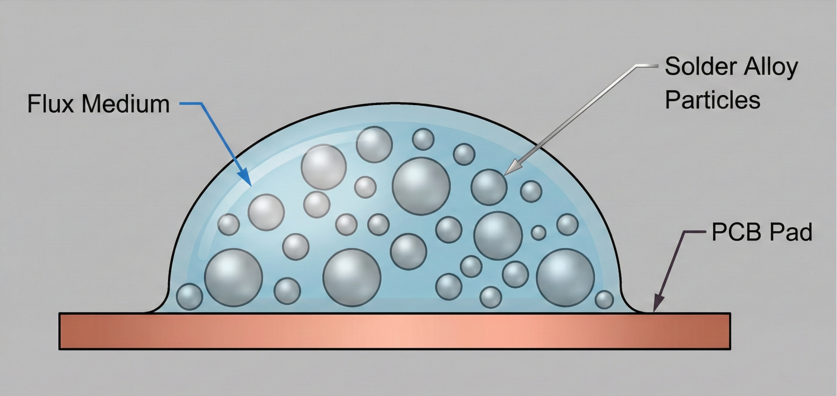
Every paste is a suspension of three things, and you control all three:
- Alloy: Sets the melting point (thermal profile) and the long-term mechanical strength/reliability of the joint.
- Flux: The engine room. It cleans the metal, prevents oxidation during heating, dictates stencil life, and determines the cleaning requirements.
- Powder Size (Type): Unlocks your ability to print fine features. It’s the gatekeeper for area ratio and volume consistency on small pads.
1.1.2 Flux Systems: No-Clean vs. Water-Soluble
This is the first major decision, impacting cost, cycle time, and risk.
Flux Family | The Production Vibe | Best Use Case | Risk & Trade-Off (The Manager View) |
No-Clean | Forgiving, long stencil life. Leaves a clear, benign (non-conductive) residue if reflow is perfect. | Most commercial, consumer, and industrial builds. Saves the cost and space of a cleaning line. | If the residue is overcooked or under-activated, it can interfere with test probes (ICT) or impact cosmetics. Must confirm residue meets cleanliness specs (IPC J-STD-004). |
Water-Soluble (WS) | Aggressive activators provide superior wetting and zero-voiding, even on oxidized surfaces. | Dense assemblies, extreme fine pitch, high-reliability builds (military/aerospace) where zero ionic residue is mandatory. | High CapEx/OpEx for the cleaning line (chemistry, utilities, wastewater). Critical risk: If cleaning is incomplete, ionic residue is aggressive and guarantees corrosion/dendritic failure in the field. |
Pro Tip: If you have wetting issues or excessive voids on BGAs, WS paste is the technical solution. But remember, you’re trading a printing problem for a costly and complex cleaning process you must now validate and control 24/7.
1.1.3 Powder Size: Matching Aperture Ratios
The powder type must be smaller than the smallest stencil aperture opening to avoid clogging. This is where your Design for Manufacturing (DFM) meets reality.
Powder Type (J-STD-005) | Particle Size Range (µm) | Use Case & Required Process Control |
Type 3 (T3) | 25 – 45 | Default, forgiving paste. Great for 0.5 mm pitch and larger. Longer stencil life, easier handling. |
Type 4 (T4) | 20 – 38 | Standard for Fine Pitch. Essential for 0.4 mm pitch QFNs and BGAs. A good balance between printability and handling. |
Type 5 (T5) | 15 – 25 | Ultra-Fine Pitch. Mandatory for 0.35 mm pitch components and the most marginal area ratios. |
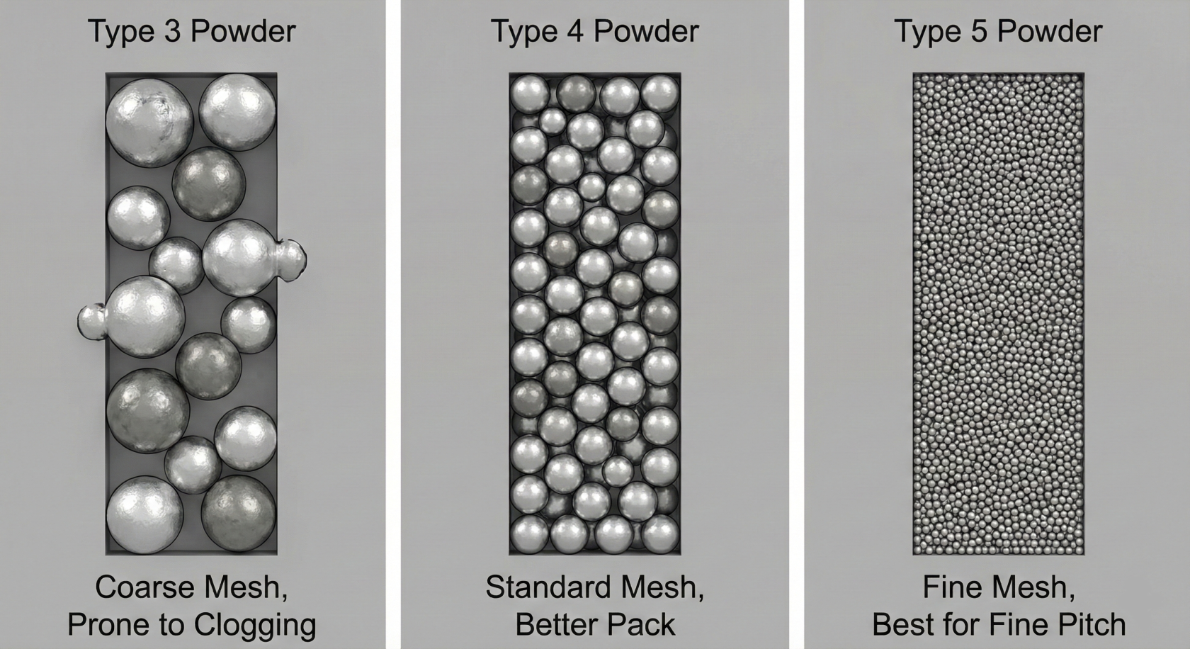
Fast Rule: If your minimum Area Ratio (Aperture Area / Aperture Wall Area) drops below 0.66, you must upgrade to the next smaller powder type (e.g., T3 – T4 – T5) to ensure consistent volume release and minimize clogging. Tighter powder means tighter storage, handling, and print control.
1.1.4 Alloy Choice: Performance, Profile, and Reliability
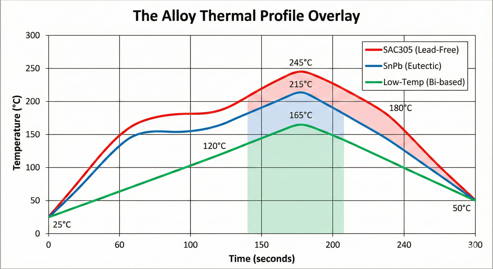
Alloy choice sets the thermal profile and, more importantly, the long-term joint integrity.
Alloy Family | Eutectic Melting Point | Process Notes (The "Vibe") | Critical Reliability Factor |
Sn63/Pb37 | ≈ 183 ˚C (Sharp, Eutectic) | Wide thermal margin, excellent wetting. | Not RoHS Compliant. Must be profiled separately. Watch out for Tin Whiskers if bare tin finishes are also present. |
SAC305 (SnAg3.0Cu0.5) | 217 ˚C (Near-Eutectic) | Industry Standard Lead-Free. Needs honest, higher profiling (longer Time Above Liquidus, TAL). Nitrogen (N2) often used to improve cosmetics and reduce voiding, especially on large thermal pads. | Superior thermal cycling fatigue resistance compared to SnPb, making it the choice for rugged, outdoor, or automotive electronics. |
Low-Temp Bi-Based | ≈ 138 – 160 ˚C (Varies) | Great for heat-sensitive parts or boards. Allows standard FR4 to be run with minimal thermal stress. | Weaker mechanically. Requires careful qualification for drop, shock, and high-vibration applications due to reduced shear strength. |
Manager Takeaway: For high-reliability, cycling applications, explore doped SAC alloys (e.g., SAC-Q, SAC-I). These specialty pastes are engineered to resist micro-cracking and improve service life where temperature extremes are a factor.
1.1.5 Mapping Your Paste to Your Process Window
The final choice must satisfy three critical axes simultaneously:
- Print Axis (Rheology & Powder): Does the paste’s rheology (its internal viscosity/flow) allow it to hold shape perfectly after the print stroke, or does it slump and cause bridging? Is the tack strong enough to hold small 0201/0402 components through conveyor travel before reflow? (Check this with SPI/AOI data.)
- Reflow Axis (Alloy & Flux): Do the chosen alloy and flux chemistry allow you to consistently hit your target TAL and Peak Temperature without oxidizing the flux or stressing the components? (Check this with thermal profiling.)
- Cleanliness Axis (Risk & Process): If you choose water-soluble, is the wash process controlled and verified to IPC standards? If you choose no-clean, do you have zero field failures related to residue, and are your test probes happy? (Check this with ionic testing and test yield data.)
When the window feels tight, resist the urge to change the operator's settings. Change the paste, the stencil, or the atmosphere (add N2) instead. Run a small Design of Experiments (DOE) to find the sweet spot, then lock it down.
1.1.8Final ReleaseChecklist: ChecklistPaste (PrintSelection This Before You Buy)Requirements
The paste selection must be verified against all process and reliability requirements before purchase.
Category
Requirement
Verification Step
Flux
Family:SystemMust meet the required cleanliness specification
Chosen(e.g., IPC J-STD-004).Cleaning process designed and validated (if WS); ICT probe test approved (if NC).
no-cleanPowder SizeType
vs.mustwater-soluble);matchcleaning process orresidue specis documented.Powder Size:Matched tothe smallestapertureaperture's Area Ratio (T3 – T4 – T5).DFM audit completed; SPI volume release verified on smallest pads.
Alloy
Must satisfy RoHS/Customer requirements and the
PCB (usually T4 for 0.5 mm, T5 for 0.35 mm).Alloy:Picked based on requiredproduct'sreliabilitythermal cycling lifespan.Profile
(thermal cycling) and confirmedverified againstthealloyavailablelimits; component maximum temperature limits guarded.Handling
Defined
reflow profilelimits.Handling:Documented rules forstorage, thawing, mixing, andopenopen-time policy in place.Standard Operating Procedure (
theSOP)maximumlockedtimeforallowedflooronstaffthe(Chapterstencil)1.2).Validation:Process MapPaste rheology verified to have sufficient tack
Plan in place to test early lots and tie results directly toSPI/AOI/AXIdata dashboardsforprocesssmallcontrol.component retention.Post-placement AOI confirms component retention through conveyor travel.